Circuit Notation
Quantum circuit diagrams are read left to right, with horizontal wires representing qubits and boxes representing gates
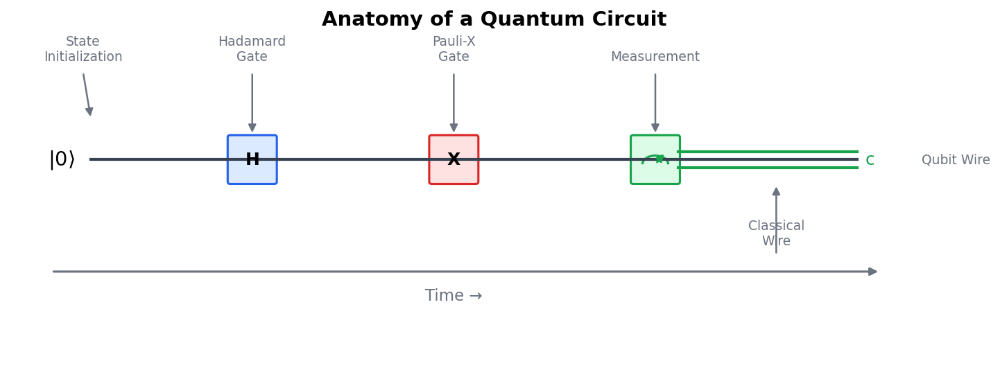
Source: mortalapps.com- Quantum circuit diagrams are read from left to right, representing the forward flow of time.
- Horizontal single lines represent quantum wires carrying individual qubits.
- Boxes on the wires represent unitary quantum gates applied to the qubits.
- The mathematical representation of a circuit sequence is written from right to left, matching the order of operator application.
- Measurement is represented by a meter symbol, which projects the quantum state and outputs a classical bit.
- Double lines represent classical wires carrying classical information (0 or 1).
- Standard quantum circuits do not allow feedback loops or backward time travel.
Why This Matters
Welcome to the visual language of quantum computing. Up to this point, we have analyzed quantum gates as isolated mathematical operators acting on individual state vectors. While this algebraic approach is rigorous, it quickly becomes unwieldy as we scale up to complex systems. To design, analyze, and communicate quantum algorithms, we use a standardized graphical representation known as quantum circuit notation.
In this topic, you will learn how to read and write quantum circuit diagrams. We will demystify the horizontal lines, boxes, and symbols that constitute a quantum circuit. By the end of this section, you will understand how time flows through a circuit, how qubits are initialized, and how operations are sequenced from left to right.
This graphical framework is not merely a convenient shorthand; it is a formal syntax used by quantum software engineers and researchers worldwide. Mastering circuit notation is your gateway to understanding complex multi-qubit algorithms, error correction protocols, and physical hardware layouts.
Core Intuition
Think of a quantum circuit diagram as a musical score. In a musical score, each horizontal line represents a specific instrument, and notes are placed along these lines from left to right to indicate when they should be played. Similarly, in a quantum circuit, each horizontal line represents a single qubit, and gates are placed along these lines to indicate when operations are applied.
Alternatively, imagine an automated assembly line. Raw materials (initialized qubits) enter on the left. As they travel along conveyor belts (wires), various robotic arms (gates) perform specific modifications in a precise sequence. Finally, at the end of the line, the finished products are inspected (measured) to yield the final output.
In both analogies, the critical dimension is time, which flows strictly from left to right. There are no loops or backward steps in a standard quantum circuit; every operation is a forward step in time, transforming the quantum state systematically.
Visualization
Technical Explanation
A quantum circuit is a graphical representation of a sequence of unitary operations and measurements on a multi-qubit system. The primary components of a quantum circuit diagram are wires, initialization symbols, gate boxes, and measurement meters. Horizontal lines represent quantum wires, each carrying a single qubit. By convention, these wires are labeled on the far left with their initial state, typically $|0\rangle$ or a general state $| \psi\rangle$.
Time flows from left to right. A gate applied to a qubit is represented by a box placed on the corresponding wire. For example, a single-qubit gate $U$ is drawn as a square box labeled '$U$' centered on the wire. If we apply gate $A$ followed by gate $B$ to a qubit, the circuit diagram shows the box for $A$ to the left of the box for $B$. Mathematically, this sequence is written as the product $B A |\psi\rangle$, because operators act from right to left on a state vector:
$$|\psi_{\text{final}}\rangle = B A |\psi_{\text{initial}}\rangle$$
Measurement is represented by a stylized meter symbol, often resembling a dial with a pointer. This operation projects the quantum state onto the computational basis, collapsing the superposition. The output of a measurement is a classical bit, which is represented by a double-line wire (classical wire) carrying the classical value $0$ or $1$.