CNOT Gate
The CNOT gate flips the target qubit if the control is |1>, and with single-qubit gates forms a universal gate set
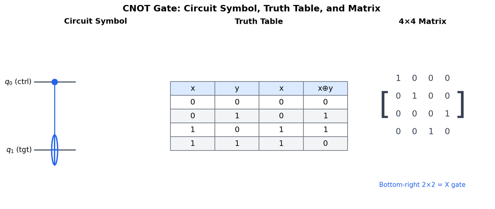
Source: mortalapps.com- The CNOT (Controlled-NOT) gate flips the target qubit if the control qubit is in state |1⟩.
- In circuit diagrams, CNOT is represented by a control dot connected to a circle-plus symbol (⊕).
- Mathematically, CNOT acts as a quantum XOR gate, mapping |x, y⟩ to |x, x ⊕ y⟩.
- The 4x4 CNOT matrix has the Pauli-X matrix in its bottom-right 2x2 block.
- Like the single-qubit X gate, the CNOT gate is its own inverse (CNOT^2 = I).
- CNOT cannot copy quantum states due to the No-Cloning Theorem.
- CNOT is the fundamental entangling gate used to couple qubits in almost all quantum algorithms.
Why This Matters
The Controlled-NOT (CNOT) gate is the workhorse of quantum computing. It is a specific controlled gate where the target operation is the Pauli-X (NOT) gate. Just as the classical NAND gate is universal for classical computing, the CNOT gate, combined with single-qubit rotations, is universal for quantum computing.
In this topic, we will dissect the CNOT gate in detail. You will learn its mathematical representation as a $4\times4$ matrix, its action on the computational basis states, and its unique circuit symbol (a control dot connected to a target circle-plus symbol). We will explore how the CNOT gate acts as a quantum XOR gate.
By the end of this topic, you will be able to calculate the output of a CNOT gate for any 2-qubit input state and understand how it manipulates the joint state vector to perform fundamental logical operations.
Core Intuition
Imagine you are teaching a friend to drive. You are in the passenger seat with an emergency brake (the control), and your friend is holding the steering wheel (the target). The rule is: 'If I pull the brake (control is $|1\rangle$), you must flip the car's direction (apply NOT to the target). If I do nothing (control is $|0\rangle$), you keep driving normally.'
In classical logic, this is exactly like an XOR (Exclusive OR) gate. The target's final state is the XOR sum of the control and the target: if the control is 1, the target flips; if the control is 0, the target stays the same.
In the quantum world, because the passenger can be in a superposition of pulling and not pulling the brake, the car enters a superposition of turning and going straight. This simple conditional flip is the key to linking the fates of the two qubits, allowing us to engineer quantum entanglement.
Visualization
Technical Explanation
The CNOT gate (also written as $CX$) applies the Pauli-X operator to the target qubit if the control qubit is in the state $|1\rangle$. In a circuit diagram, the control qubit has a solid dot, and the target qubit has a circle-plus symbol ($\oplus$), which represents addition modulo 2 (XOR).
Its action on the computational basis states is defined as: $$|00\rangle \xrightarrow{\text{CNOT}} |00\rangle$$ $$|01\rangle \xrightarrow{\text{CNOT}} |01\rangle$$ $$|10\rangle \xrightarrow{\text{CNOT}} |11\rangle$$ $$|11\rangle \xrightarrow{\text{CNOT}} |10\rangle$$
In general, for basis states $|x, y\rangle$ where $x, y \in \{0, 1\}$, the output is $|x, x \oplus y\rangle$, where $\oplus$ is the XOR operation. Written as a $4\times4$ matrix in the computational basis ($|00\rangle, |01\rangle, |10\rangle, |11\rangle$), the CNOT matrix is:
$$\text{CNOT} = \begin{pmatrix} 1 & 0 & 0 & 0 \\ 0 & 1 & 0 & 0 \\ 0 & 0 & 0 & 1 \\ 0 & 0 & 1 & 0 \end{pmatrix}$$
Notice that the bottom-right 2x2 block is the Pauli-X matrix: $\begin{pmatrix} 0 & 1 \\ 1 & 0 \end{pmatrix}$. Like the single-qubit X gate, the CNOT gate is its own inverse: $\text{CNOT}^2 = I$.