Controlled Gates
Controlled gates apply a unitary operation to a target qubit only when the control qubit is in state |1>
Source: mortalapps.com- Controlled gates use one qubit (control) to determine whether an operation is applied to another qubit (target).
- In circuit diagrams, a solid dot represents the control, connected by a vertical line to the target gate.
- If the control is |0⟩, the target is unchanged; if the control is |1⟩, the unitary U is applied.
- Mathematically, a Controlled-U gate is represented by a 4x4 block-diagonal matrix.
- The top-left block of a Controlled-U matrix is always the 2x2 Identity matrix.
- Controlled gates do not measure or destroy the control qubit; they preserve quantum coherence.
- Controlled gates are the fundamental mechanism for creating interactions and entanglement between qubits.
Why This Matters
In classical computing, conditional logic is fundamental: 'if condition is true, then perform action.' In quantum computing, we implement this conditional logic using controlled gates. Controlled gates are multi-qubit operations where one qubit (the control) dictates whether a specific unitary operation is applied to another qubit (the target).
In this topic, we will explore the general concept of controlled gates in quantum circuits. You will learn how these gates are represented visually with control dots and target boxes, and how they are constructed mathematically as block-diagonal matrices. We will examine how controlled gates allow us to build conditional logic directly into the quantum state space.
By the end of this topic, you will understand the general structure of controlled-U gates, how to read their circuit symbols, and how to construct their $4\times4$ matrix representations for any single-qubit unitary $U$.
Core Intuition
Think of a controlled gate as a smart home automation rule. You have a motion sensor (the control qubit) and a light bulb (the target qubit). The rule says: 'If the motion sensor detects movement (is in state $|1\rangle$), then turn on the light (apply the flip operation to the target). If the sensor detects nothing (is in state $|0\rangle$), do nothing to the light.'
In the classical world, the sensor is either ON or OFF. But in the quantum world, the control qubit can be in a superposition of $|0\rangle$ and $|1\rangle$. This means the gate is applied and not applied *simultaneously*.
This creates a profound quantum phenomenon: the control and target qubits become deeply linked. The gate doesn't just check the control and modify the target; it creates a joint, inseparable state where the identity of each qubit is bound to the other.
Visualization
Technical Explanation
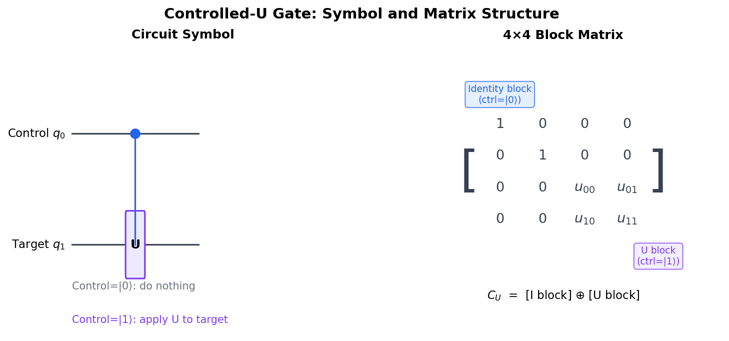
A controlled gate has at least one control qubit and one target qubit. The most general form is the Controlled-U gate, where $U$ is any single-qubit unitary operator. In a circuit diagram, a solid black dot is placed on the control wire, and a vertical line connects it to a box containing '$U$' on the target wire.
If the control qubit is in state $|0\rangle$, the target qubit remains unchanged (the Identity operator $I$ is applied). If the control qubit is in state $|1\rangle$, the unitary $U$ is applied to the target qubit. Mathematically, we can write this conditional operation as:
$$P_0 \otimes I + P_1 \otimes U$$
where $P_0 = |0\rangle\langle 0|$ and $P_1 = |1\rangle\langle 1|$ are the projection operators onto the $|0\rangle$ and $|1\rangle$ states of the control qubit. Written as a $4\times4$ matrix in the computational basis ($|00\rangle, |01\rangle, |10\rangle, |11\rangle$), the Controlled-U gate has a block-diagonal structure:
$$C(U) = \begin{pmatrix} 1 & 0 & 0 & 0 \\ 0 & 1 & 0 & 0 \\ 0 & 0 & u_{00} & u_{01} \\ 0 & 0 & u_{10} & u_{11} \end{pmatrix} = \begin{pmatrix} I & 0 \\ 0 & U \end{pmatrix}$$
where $I$ is the $2\times2$ identity matrix and $U = \begin{pmatrix} u_{00} & u_{01} \\ u_{10} & u_{11} \end{pmatrix}$ is the unitary matrix of the target operation.