Single-Qubit Circuits
A single-qubit circuit multiplies gate matrices right to left, tracing a path of rotations across the Bloch sphere
Source: mortalapps.com- A single-qubit circuit consists of a sequence of operations applied to a single quantum wire.
- The cumulative effect of a sequence of gates is calculated by multiplying their matrices from right to left.
- Any sequence of single-qubit gates is mathematically equivalent to a single rotation on the Bloch sphere.
- Gates do not generally commute; changing the order of gates changes the final state.
- Some gates (like H, X, Y, Z) are their own self-inverse, meaning applying them twice in succession does nothing.
- Phase gates (S, T) modify the relative phase of a superposition without changing computational basis measurement probabilities.
- Compilers optimize circuits by merging consecutive single-qubit gates into a single physical operation.
Why This Matters
Now that we have mastered the basic syntax of quantum circuit notation, we will apply it to single-qubit systems. A single-qubit circuit consists of a single horizontal wire along which we apply a sequence of single-qubit gates. While seemingly simple, single-qubit circuits are the building blocks of all quantum algorithms and allow us to explore the rich geometry of the Bloch sphere.
In this topic, we will analyze how sequences of gates manipulate a single qubit's state. We will learn how to calculate the cumulative effect of multiple gates by multiplying their corresponding 2x2 matrices. This will solidify your ability to trace a quantum state's trajectory mathematically and visually.
By the end of this topic, you will be able to design single-qubit circuits that prepare any desired superposition state from a standard $|0\rangle$ input, and you will understand how successive rotations combine to form a single equivalent rotation.
Core Intuition
Imagine a single qubit as a spaceship navigating the surface of a globe (the Bloch sphere). The spaceship starts at the North Pole ($|0\rangle$). A single-qubit circuit is a flight plan consisting of a sequence of instructions: 'rotate 180 degrees around the X-axis' (X gate), 'rotate 90 degrees around the Z-axis' (S gate), or 'perform a 180-degree flip around the diagonal X+Z axis' (Hadamard gate).
Each gate in the circuit is a specific maneuver. Tracing the circuit means tracking the spaceship's position after each maneuver. No matter how many maneuvers the spaceship performs, it always ends up at some specific point on the globe.
This highlights a key mathematical fact: any sequence of single-qubit gates, no matter how long, can always be compressed into a single, equivalent rotation around some axis of the Bloch sphere. The circuit is simply a practical way to break down this complex rotation into standard, easy-to-implement steps.
Visualization
Technical Explanation
Mathematically, a single-qubit circuit with $n$ gates applied in sequence to an initial state $|\psi_0\rangle$ is represented by the composition of $n$ unitary matrices. Let the gates be $U_1, U_2, \dots, U_n$ in order of appearance from left to right. The state evolves as follows:
$$|\psi_1\rangle = U_1 |\psi_0\rangle$$ $$|\psi_2\rangle = U_2 |\psi_1\rangle = U_2 U_1 |\psi_0\rangle$$ $$\dots$$ $$|\psi_n\rangle = U_n U_{n-1} \dots U_1 |\psi_0\rangle$$
Because the product of any number of unitary matrices is itself a unitary matrix, we can define a single effective unitary operator $U_{\text{eff}} = U_n U_{n-1} \dots U_1$. Thus, $|\psi_n\rangle = U_{\text{eff}} |\psi_0\rangle$.
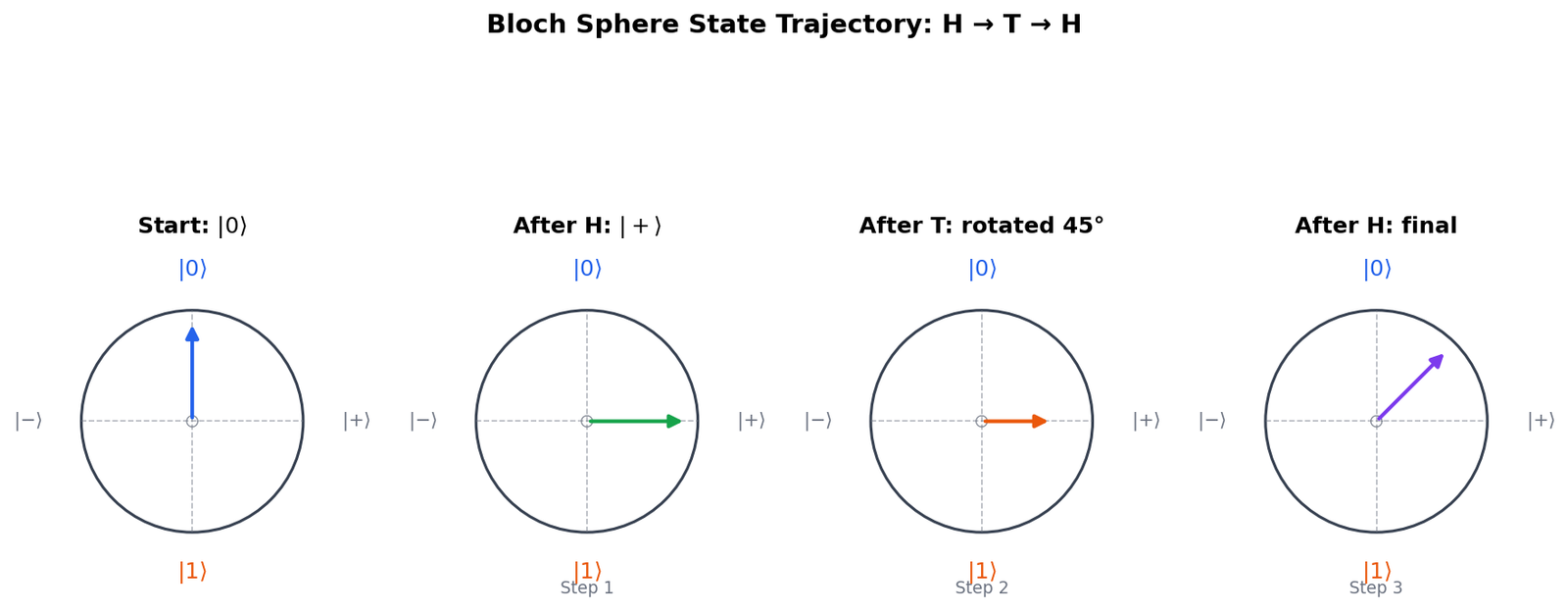
Let us look at a concrete example. Suppose we initialize a qubit to $|0\rangle$ and apply an $H$ gate followed by a $T$ gate. The circuit diagram shows a wire with an $H$ box followed by a $T$ box. The mathematical calculation is:
$$|\psi_{\text{final}}\rangle = T H |0\rangle = \begin{pmatrix} 1 & 0 \\ 0 & e^{i\pi/4} \end{pmatrix} \frac{1}{\sqrt{2}} \begin{pmatrix} 1 & 1 \\ 1 & -1 \end{pmatrix} \begin{pmatrix} 1 \\ 0 \end{pmatrix} = \frac{1}{\sqrt{2}} \begin{pmatrix} 1 \\ e^{i\pi/4} \end{pmatrix}$$
This state is a superposition with equal probabilities of measuring $0$ or $1$, but with a relative phase of $\pi/4$ (or $45^\circ$) between them.